Robotic Wrist Exoskeleton with IMU Feedback
As part of an undergraduate final-year project, this innovative wrist exoskeleton is powered by six twisted string actuators, an affordable and efficient solution capable of generating large strokes. The lightweight device allows full wrist movement across three degrees of freedom, offering a wide range of motion. Real-time visual feedback is provided by two 9-axis MPU9250 IMU sensors using the Madgwick Filter for precise motion tracking, while a virtual environment created with UPBGE software enhances user interaction. The orthosis has the potential for wrist movement rehabilitation, combining functionality with cost-effectiveness, and will be presented at RCAE 2024 and published in the conference proceedings.
Explore a lightweight and affordable wrist exoskeleton designed to support full mobility and provide real-time feedback, offering a practical solution for wrist movement rehabilitation!
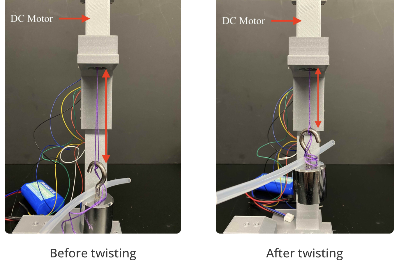
Twisted String Actuator
The working principle of the twisted string actuator is simple: one or more threads are arranged in parallel, with one end connected to a rotating DC motor and the other end attached to the load. When the motor rotates while the load’s rotation is restricted, the threads twist together, shortening their length by up to 30% of the original, resulting in linear movement of the load. This mechanism not only allows for large strokes but also enables the actuator to pull much heavier loads compared to directly using the motor’s torque.
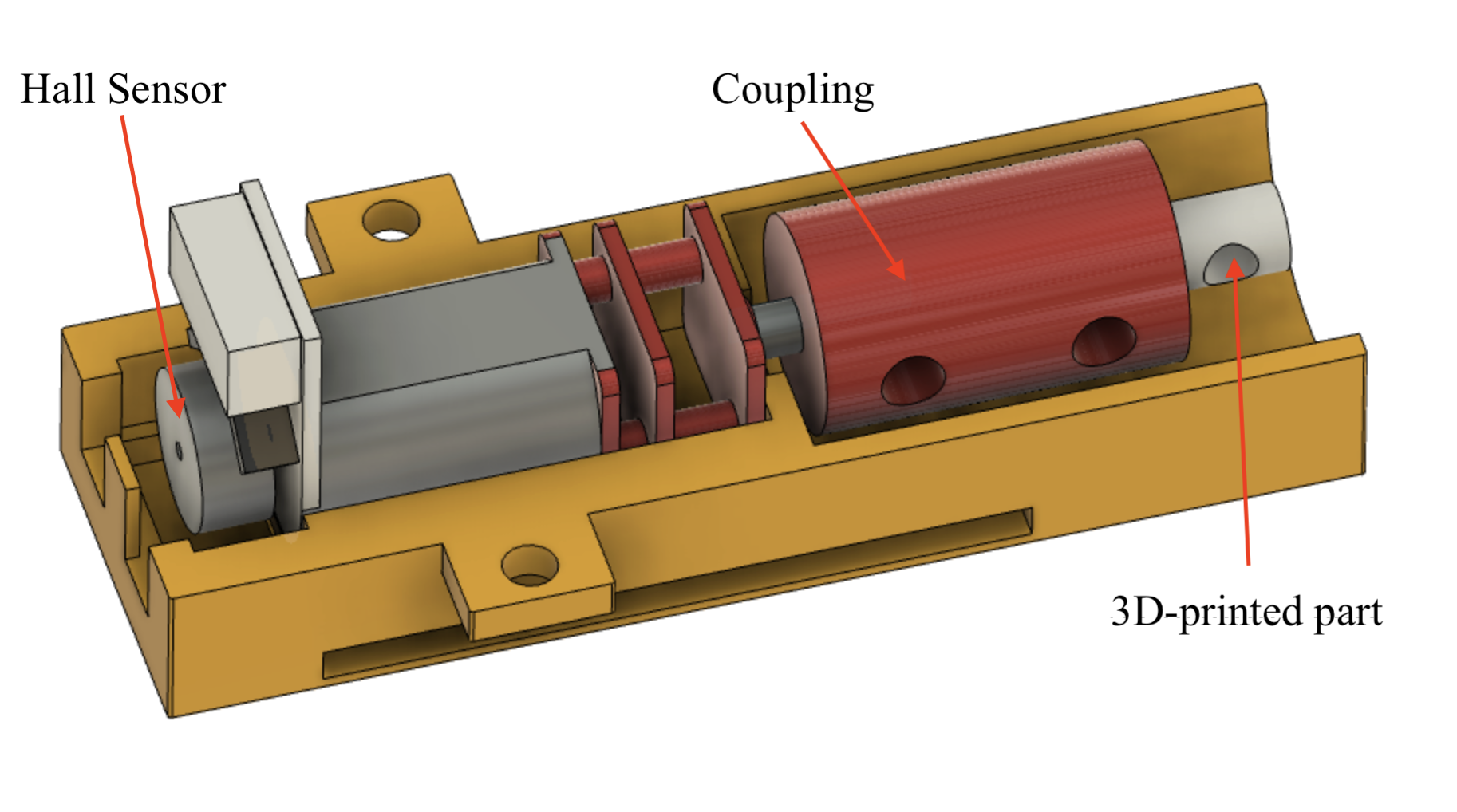
The motor used in this project is a 12V N20 DC motor equipped with a Hall encoder. The motor measures approximately 40 mm x 19 mm x 12 mm. The encoder, located at the rear of the motor, records the number of revolutions during actuator operation. The threads used are fishing lines.
The process of constructing the twisted string actuator is as follows: first, connect the motor’s output shaft to a coupling, which is then attached to a 3D-printed component designed for securing the threads. One end of the thread is tied to this 3D-printed part, while a load is attached to the other end. The motor is then allowed to rotate, with the load’s rotation restricted, generating linear movement.
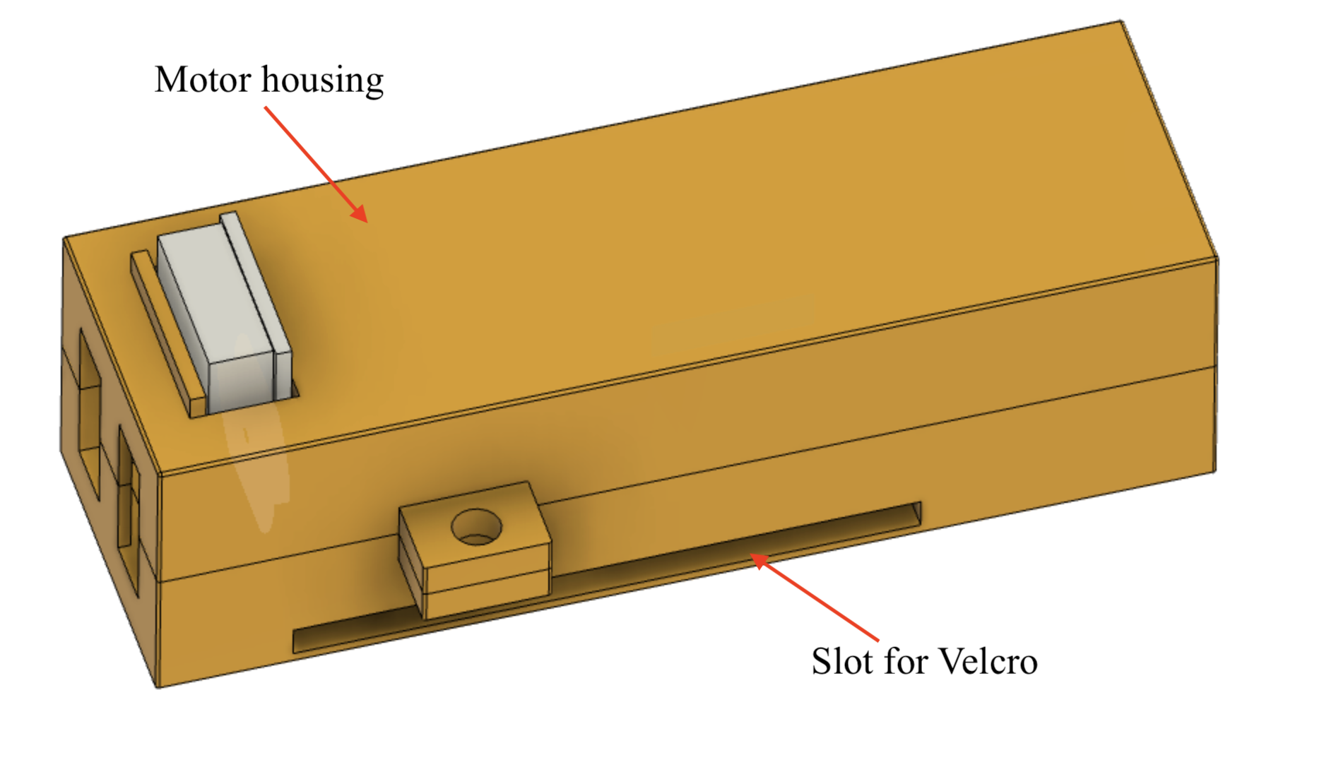
A housing is designed for the motor, consisting of two parts: a top and a bottom, which are secured together using bolts. The housing includes a slot for Velcro to pass through, allowing multiple actuators to be attached to the same Velcro strip.
Assembly of Multiple Actuators
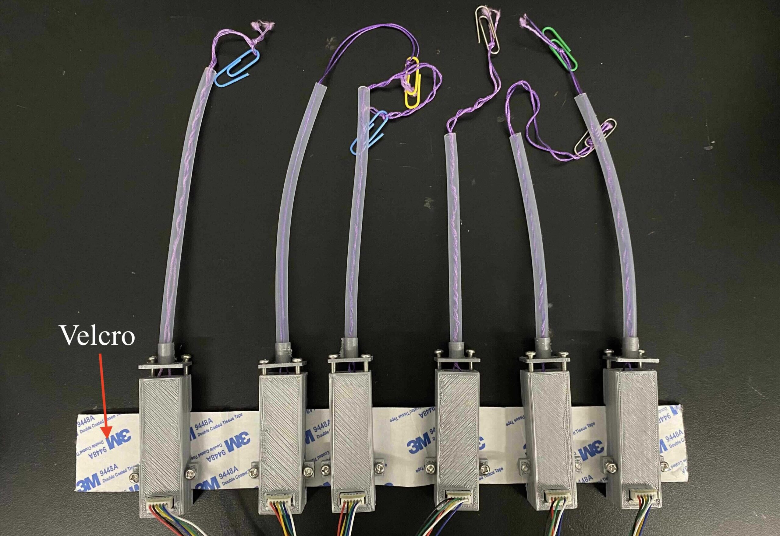
In each actuator, a silicone tube separates the threads from the wearer’s arm, preventing direct contact. A paper clip at the end connects the actuator to the wrist orthosis. Multiple twisted string actuators are assembled using Velcro threaded through each actuator’s housing slot. The friction between the Velcro and the actuator is sufficient to prevent sliding while still allowing easy adjustment of the actuator’s position along the Velcro.
To attach six actuators to the wearer’s arm, the user first wraps a Velcro strap around their arm near the elbow joint. Then, the Velcro strip with the six twisted string actuators is attached to the strap already on the arm. This Velcro system makes it easy to put on and remove the actuators while effectively securing them in place. Additionally, users can adjust the tightness of the Velcro and the position of the actuators to comfortably fit the size of their arm.
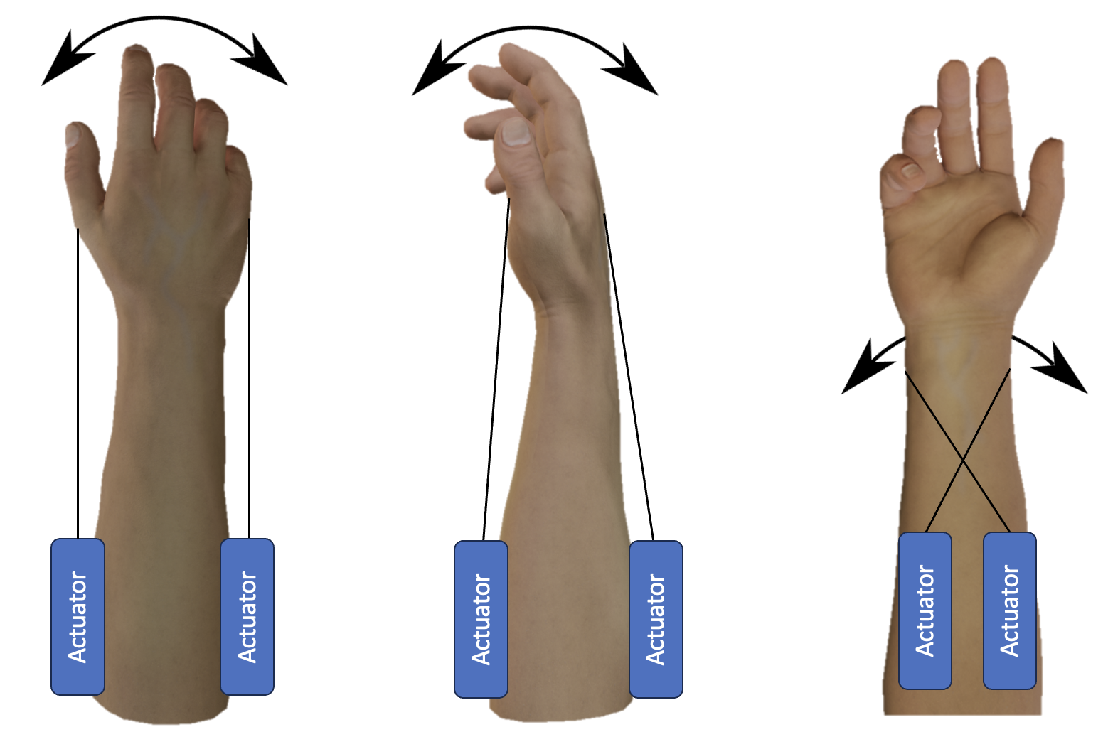
The human wrist has three degrees of freedom. Because a twisted string actuator generates pulling force only when twisting (driving) and does not produce pushing force when untwisting, each degree of freedom is controlled by a pair of actuators. While one actuator drives by twisting and pulling, the other unwinds.




IMU feedback
An Inertial Measurement Unit (IMU) is a sensor that measures acceleration, angular velocity, and magnetic field strength to determine the orientation of objects. Typically small and lightweight, IMUs are widely used in wearable devices, robotics, aerospace, autonomous vehicles, and other fields.
IMUs are generally classified as six-axis or nine-axis devices. A six-axis IMU includes a three-axis accelerometer and a three-axis gyroscope, while a nine-axis IMU adds a three-axis magnetometer. While a six-axis IMU can measure an object’s orientation relative to Earth’s gravity, a nine-axis IMU provides complete attitude information by also measuring the magnetic field orientation. Since this project requires capturing wrist movement in three degrees of freedom and obtaining the full pose of the hand and forearm, a nine-axis IMU—the MPU9250—was chosen.
The IMUs are attached to the orthosis using Velcro. One IMU is placed on the back of the hand, while the other is positioned on the forearm near the wrist.
Madgwick Filter
The Madgwick filter is an orientation estimation algorithm that fuses data from an accelerometer, gyroscope, and magnetometer to provide accurate real-time orientation tracking. It is particularly efficient in low-computation environments, making it ideal for embedded systems and wearable devices. Compared to the complementary filter, the Madgwick filter has faster convergence and offers better performance, especially during dynamic movements. Using only an accelerometer can lead to noisy data, while relying solely on a gyroscope introduces drift over time. The Madgwick filter combines the advantages of both, offering stable and accurate orientation estimates by compensating for the weaknesses of each individual sensor. In this project, the Madgwick filter is used to enhance the precision of wrist movement tracking and obtain reliable pose data for the hand and forearm.
Demonstration of the Exoskeleton on a 3D-Printed Arm and a Real Human Arm
The test results demonstrate that the wrist exoskeleton can effectively control flexion and extension, adduction and abduction, as well as pronation and supination of the human wrist. The total range of motion achieved is 122° for flexion and extension, 61° for adduction and abduction, and 86° for pronation and supination, respectively.
Publication
The project will be presented at The 7th International Conference on Robotics, Control, and Automation Engineering (RCAE 2024) and published in the RCAE 2024 Conference Proceedings.