KUKA youBot Simulation
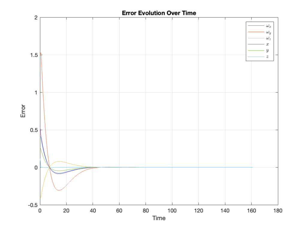
In the final project of the MAE 204 Robotics class at UCSD, the task was to control the youBot, a mobile manipulator robot with a 5R arm and Mecanum wheels, to pick up an object and place it in a designated area. The process involved defining waypoints for the robot’s end effector, calculating error twists and Jacobians, and updating the robot’s state while checking for joint limit violations. The project explored feedforward and PI feedback control techniques, to achieve both overshoot and no overshoot in velocity errors. The control system was developed using MATLAB, and simulations were run in CoppeliaSim.
Discover how different techniques were applied to guide the youBot in this project, highlighting trajectory generation, youBot kinematics, and feedforward and feedback control
This project is similar to the Mobile Manipulation Capstone from Prof. Kevin Lynch’s course on Robotic Manipulation.


Trajectory Generation
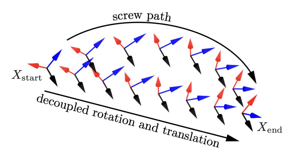
The trajectory generation process for the youBot involves defining a sequence of waypoints that represent the desired path for the robot’s end effector. These waypoints include the specific locations where the youBot will grab the object and where it will place it. Once the waypoints are defined, trajectories connecting these points are generated by decoupling the rotation and translation motions. To ensure smooth and efficient motion, quintic (fifth-order polynomial) time scaling is applied, which provides continuous acceleration and velocity profiles, reducing abrupt changes in movement.
Screw Motion vs. Decoupled Rotation and Translation Motion
Let the start and end configurations be \(X_{\text{start}}\) and \(X_{\text{end}}\) in the task space. The path from \(X_{\text{start}}\) to \(X_{\text{end}}\) can be expressed as:
\[
X(s) = X_{\text{start}} \exp(\log(X_{\text{start}}^{-1} X_{\text{end}})s), \quad s \in [0, 1].
\]
This describes a screw motion with a constant screw axis, though the end-effector’s origin does not generally follow a straight line in Cartesian space. To separate rotational and translational motions, define \(X = (R, p)\) and the path as:
\[
p(s) = p_{\text{start}} + s(p_{\text{end}} – p_{\text{start}}) \]
\[R(s) = R_{\text{start}} \exp(\log(R_{\text{start}}^T R_{\text{end}})s)
\]
where the origin follows a straight line, and the rotation axis stays constant in the body frame.
Fifth-order Polynomials Time Scaling
A smooth form for the time scaling \(s(t)\) is a fifth-order polynomial of time:
\[
s(t) = a_0 + a_1 t + a_2 t^2 + a_3 t^3 + a_4 t^4 + a_5 t^5
\]
with the constraints \(s(0) = \dot{s}(0) = \ddot{s}(0) = 0\), \(s(T) = 1\), \(\dot{s}(T) = \ddot{s}(T) = 0\). These constraints ensure that the velocity and acceleration do not experience discontinuous jumps, unlike the third-order polynomial.
youBot Kinematics
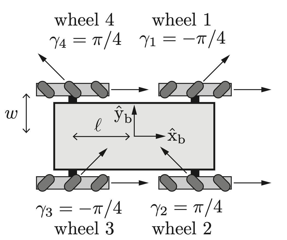
The kinematic model of the mobile robot with four Mecanum wheels is:
\[
\begin{bmatrix}
u_1 \\
u_2 \\
u_3 \\
u_4
\end{bmatrix}
= \frac{1}{r}
\begin{bmatrix}
-l – w & 1 & -1 \\
l + w & 1 & 1 \\
l + w & 1 & -1 \\
-l – w & 1 & 1
\end{bmatrix}
\begin{bmatrix}
\omega_{bz} \\
v_{bx} \\
v_{by}
\end{bmatrix}
\]
where \(u_1, u_2, u_3,\) and \(u_4\) are the speeds of the four wheels, and \(\omega_{bz}, v_{bx}, v_{by}\) are the angular velocity and linear velocities of the robot. To move in the \(+\hat{x}_b\) direction, all wheels drive forward at the same speed. To move in the \(+\hat{y}_b\) direction, wheels 1 and 3 drive backward, and wheels 2 and 4 drive forward at the same speed. To rotate counterclockwise, wheels 1 and 4 drive backward, and wheels 2 and 3 drive forward at the same speed.
Feedforward and PI Control Law
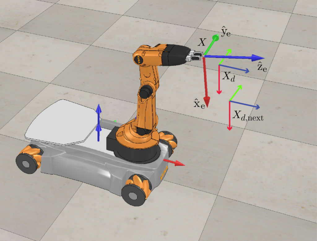
The feedforward and PI feedback control law is written as:
\[
\mathcal{V}_e(t) = [\text{Ad}_{(X^{-1}X_d)}] \mathcal{V}_d(t) + k_p X_e(t) + k_i \int_{0}^{t} X_e(\tau) \, d\tau
\]
where:
– \(X\) is the current actual end-effector configuration,
– \(X_d\) is the current end-effector reference configuration,
– \(X_{d, \text{next}}\) is the end-effector reference configuration at the next timestep in the reference trajectory, at a time \(\Delta t\) later,
– \(k_p\) and \(k_i\) are the PI gains,
– \(\mathcal{V}_e\) is the commanded end-effector twist expressed in the end-effector frame \(\{e\}\),
– \(\mathcal{V}_d\) is the feedforward reference twist that takes \(X_d\) to \(X_{d, \text{next}}\) in time \(\Delta t\), which is extracted from:
\[
\mathcal{V}_d = \frac{1}{\Delta t} \log(X_d^{-1}X_{d, \text{next}})
\]
To convert \(\mathcal{V}_e\) into the commanded wheel and arm joint speeds \((u, \dot{\theta})\), the pseudoinverse of the mobile manipulator Jacobian \(J_e(\theta)\) is used:
\[
\begin{bmatrix}
u \\
\dot{\theta}
\end{bmatrix}
=
J_e^{\dagger}(\theta) \mathcal{V}_e
\]
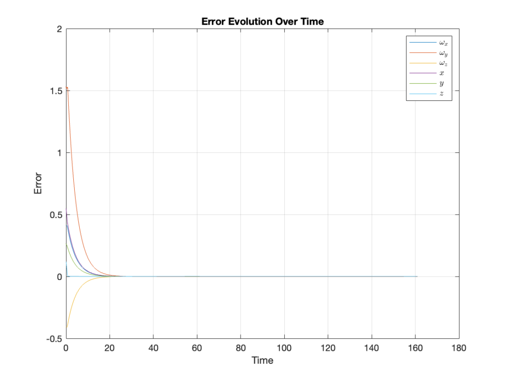
Video Demonstration: Error Overshoot
Video Demonstration: Error No Overshoot
